

How To Clean A Sooted Secondary Heat Exchanger
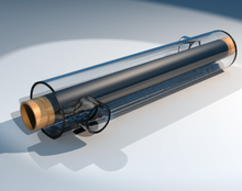

Partial view into inlet plenum of trounce and tube rut exchanger of a refrigerant based chiller for providing air-conditioning to a building
A heat exchanger is a system used to transfer oestrus between two or more fluids. Heat exchangers are used in both cooling and heating processes.[1] The fluids may be separated by a solid wall to prevent mixing or they may be in directly contact.[two] They are widely used in space heating, refrigeration, air conditioning, power stations, chemical plants, petrochemical plants, petroleum refineries, natural-gas processing, and sewage treatment. The classic example of a heat exchanger is found in an internal combustion engine in which a circulating fluid known as engine coolant flows through radiator coils and air flows past the coils, which cools the coolant and heats the incoming air. Another example is the heat sink, which is a passive estrus exchanger that transfers the estrus generated past an electronic or a mechanical device to a fluid medium, oft air or a liquid coolant.[3]
Menstruation arrangement [edit]

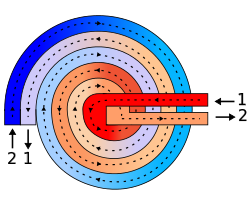
Countercurrent (A) and parallel (B) flows
-
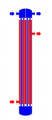
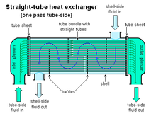
Fig. 2: Vanquish and tube heat exchanger, ii-pass tube side (ane–two crossflow)
-

Fig. 3: Beat out and tube oestrus exchanger, 2-pass shell side, 2-pass tube side (2-2 countercurrent)
There are three main classifications of rut exchangers according to their period arrangement. In parallel-menses heat exchangers, the two fluids enter the exchanger at the same cease, and travel in parallel to one another to the other side. In counter-menstruum heat exchangers the fluids enter the exchanger from opposite ends. The counter current design is the most efficient, in that it can transfer the about estrus from the rut (transfer) medium per unit mass due to the fact that the average temperature departure forth any unit length is higher. See countercurrent exchange. In a cross-flow rut exchanger, the fluids travel roughly perpendicular to one some other through the exchanger.
For efficiency, heat exchangers are designed to maximize the surface expanse of the wall between the ii fluids, while minimizing resistance to fluid flow through the exchanger. The exchanger'southward performance can also exist affected by the addition of fins or corrugations in one or both directions, which increase surface area and may channel fluid menstruum or induce turbulence.
The driving temperature across the estrus transfer surface varies with position, but an appropriate mean temperature tin can exist defined. In well-nigh uncomplicated systems this is the "log mean temperature difference" (LMTD). Sometimes direct knowledge of the LMTD is non bachelor and the NTU method is used.
Types [edit]
Double piping heat exchangers are the simplest exchangers used in industries. On one hand, these heat exchangers are inexpensive for both design and maintenance, making them a good choice for small industries. On the other hand, their depression efficiency coupled with the high space occupied in large scales, has led modern industries to use more than efficient rut exchangers like vanquish and tube or plate. Notwithstanding, since double pipe estrus exchangers are simple, they are used to teach heat exchanger design basics to students equally the fundamental rules for all heat exchangers are the same.
ane. Double-pipe rut exchanger (a) When the other fluid flows into the annular gap between ii tubes, ane fluid flows through the smaller pipe. The flow may be a current flow or parallel menses in a double pipe heat exchanger. (b) Parallel menses, where at the same point, the hot and cold liquids join, flow in the same direction and exit at the same cease.
(c) Counter menstruum, where at contrary ends, hot and cold fluids join, flow in the opposite management and exit at reverse ends.
The figure to a higher place illustrates the parallel and counter-menstruum catamenia directions of the fluid exchanger. If this is done under comparable conditions, more estrus is transferred to the counter-menstruation device than to the parallel menstruation heat exchanger. Owing to the big temperature differential arising from the high thermal voltage, the temperature profiles of the two heat exchangers display ii significant disadvantages in the parallel-catamenia pattern. Which indicates that the partnership is a distinct disadvantage if information technology is intended a design is to increase the cold fluid temperature. Where 2 fluids are expected to be taken to exactly the same temperature, the parallel flow configuration is benign. While the counter flow heat exchanger has more significant advantages compare to parallel flow design. Where it can reduce thermal stress and produce more uniform rate of oestrus transfer.
2. Beat-and-tube heat exchanger
The main constituents of this type of heat exchanger seem to be the tube box, crush, the front rear end headers, and baffles or fins.
The baffles are used to back up the tubes, straight the fluid flow to the tubes in an approximately natural manner, and maximize the turbulence of the beat fluid. At that place is many various kinds of baffles, and the choice of baffle form, spacing, and geometry depending on the allowable flow rate of the drop in beat out-side force, the need for tube back up, and the menstruation-induced vibrations. In that location are several variations of shell-and-tube exchangers available; the differences prevarication in the arrangement of catamenia configurations and details of structure.
In application to cool air with beat-and-tube engineering science (such as intercooler / accuse air cooler for combustion engines), fins tin exist added on the tubes to increase rut transfer expanse on air side and create a tubes & fins configuration.
3. Plate Heat Exchanger A plate oestrus exchanger contains an amount of thin shaped heat transfer plates bundled together. The gasket arrangement of each pair of plates provides ii carve up aqueduct organisation. Each pair of plates form a aqueduct where the fluid can catamenia through. The pairs are attached by welding and bolting methods. The following shows the components in the heat exchanger.
In single channels the configuration of the gaskets enables flow through. Thus, this allows the main and secondary media in counter-current menses. A gasket plate heat exchanger has a heat region from corrugated plates. The gasket function as seal between plates and they are located betwixt frame and pressure plates. Fluid flows in a counter current direction throughout the heat exchanger. An efficient thermal performance is produced. Plates are produced in different depths, sizes and corrugated shapes. There is different type of plates available which includes plate and frame, plate and shell and spiral plate heat exchangers. The distribution area guarantees the flow of fluid to the whole heat transfer surface. This helps to prevent stagnant area that can cause accumulation of unwanted material on solid surfaces. Loftier catamenia turbulence between plates results in a greater transfer of heat and a decrease in pressure level.
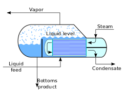
4. Condensers and Boilers Heat exchangers using a 2-phase heat transfer arrangement are condensers, boilers and evaporators. Condensers are instruments that take and cool hot gas or vapor to the point of condensation and transform the gas into a liquid class. The point at which liquid transforms to gas is called vaporization and vice versa is called condensation. Surface condenser is the nearly common type of condenser where information technology includes a water supply device. Figure v below displays a 2-laissez passer surface condenser.
The pressure of steam at the turbine outlet is low where the steam density is very depression where the flow charge per unit is very high. To prevent a decrease in force per unit area in the movement of steam from the turbine to condenser, the condenser unit is placed underneath and connected to the turbine. Inside the tubes the cooling water runs in a parallel style, while steam moves in a vertical downward position from the wide opening at the top and travel through the tube. Furthermore, boilers are categorized as initial application of heat exchangers. The word steam generator was regularly used to draw a banality unit where a hot liquid stream is the source of heat rather than the combustion products. Depending on the dimensions and configurations the boilers are manufactured. Several boilers are just able to produce hot fluid while on the other hand the others are manufactured for steam production.
Crush and tube heat exchanger [edit]
A beat and tube heat exchanger

Shell and tube heat exchanger
Shell and tube heat exchangers consist of a series of tubes which comprise fluid that must be either heated or cooled. A second fluid runs over the tubes that are being heated or cooled so that it can either provide the heat or absorb the rut required. A set of tubes is called the tube packet and tin be fabricated upwards of several types of tubes: plain, longitudinally finned, etc. Shell and tube heat exchangers are typically used for high-pressure applications (with pressures greater than 30 bar and temperatures greater than 260 °C).[four] This is considering the trounce and tube heat exchangers are robust due to their shape.
Several thermal design features must be considered when designing the tubes in the beat and tube heat exchangers: There can exist many variations on the crush and tube blueprint. Typically, the ends of each tube are continued to plenums (sometimes chosen h2o boxes) through holes in tubesheets. The tubes may exist straight or bent in the shape of a U, chosen U-tubes.
- Tube diameter: Using a small tube diameter makes the estrus exchanger both economic and compact. However, it is more probable for the heat exchanger to foul up faster and the small size makes mechanical cleaning of the fouling hard. To prevail over the fouling and cleaning problems, larger tube diameters can be used. Thus to determine the tube diameter, the available infinite, cost and fouling nature of the fluids must be considered.
- Tube thickness: The thickness of the wall of the tubes is usually determined to ensure:
- There is enough room for corrosion
- That menstruum-induced vibration has resistance
- Axial forcefulness
- Availability of spare parts
- Hoop strength (to withstand internal tube pressure level)
- Buckling force (to withstand overpressure in the shell)
- Tube length: heat exchangers are usually cheaper when they take a smaller shell diameter and a long tube length. Thus, typically at that place is an aim to make the rut exchanger as long equally physically possible whilst not exceeding product capabilities. However, there are many limitations for this, including space available at the installation site and the demand to ensure tubes are available in lengths that are twice the required length (then they tin exist withdrawn and replaced). As well, long, thin tubes are difficult to take out and supercede.
- Tube pitch: when designing the tubes, information technology is practical to ensure that the tube pitch (i.e., the centre-middle distance of bordering tubes) is not less than 1.25 times the tubes' exterior diameter. A larger tube pitch leads to a larger overall shell diameter, which leads to a more expensive heat exchanger.
- Tube corrugation: this type of tubes, mainly used for the inner tubes, increases the turbulence of the fluids and the effect is very important in the rut transfer giving a improve functioning.
- Tube Layout: refers to how tubes are positioned inside the beat. There are four main types of tube layout, which are, triangular (30°), rotated triangular (threescore°), square (90°) and rotated foursquare (45°). The triangular patterns are employed to give greater heat transfer as they force the fluid to catamenia in a more turbulent fashion around the piping. Foursquare patterns are employed where high fouling is experienced and cleaning is more than regular.
- Baffle Design: baffles are used in shell and tube heat exchangers to straight fluid across the tube bundle. They run perpendicularly to the vanquish and agree the packet, preventing the tubes from sagging over a long length. They can too foreclose the tubes from vibrating. The most common blazon of baffle is the segmental baffle. The semicircular segmental baffles are oriented at 180 degrees to the adjacent baffles forcing the fluid to menses upward and downwards betwixt the tube packet. Baffle spacing is of large thermodynamic concern when designing vanquish and tube rut exchangers. Baffles must be spaced with consideration for the conversion of pressure drib and heat transfer. For thermo economic optimization it is suggested that the baffles exist spaced no closer than xx% of the beat out'due south inner bore. Having baffles spaced too closely causes a greater pressure drop because of flow redirection. Consequently, having the baffles spaced as well far autonomously means that there may be cooler spots in the corners betwixt baffles. It is as well of import to ensure the baffles are spaced shut enough that the tubes do not sag. The other chief type of baffle is the disc and doughnut bamboozle, which consists of two concentric baffles. An outer, wider baffle looks similar a doughnut, whilst the inner baffle is shaped like a disk. This blazon of baffle forces the fluid to pass around each side of the disk so through the doughnut baffle generating a different type of fluid flow.
- Tubes & fins Pattern: in application to cool air with shell-and-tube technology (such as intercooler / charge air cooler for combustion engines), the difference in heat transfer between air and cold fluid tin can exist such that there is a need to increment rut transfer surface area on air side. For this function fins can be added on the tubes to increase heat transfer expanse on air side and create a tubes & fins configuration.
Fixed tube liquid-cooled heat exchangers specially suitable for marine and harsh applications can be assembled with brass shells, copper tubes, brass baffles, and forged brass integral end hubs.[ citation needed ] (Encounter: Copper in heat exchangers).

Conceptual diagram of a plate and frame oestrus exchanger.
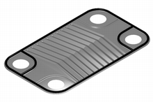
A unmarried plate heat exchanger

An interchangeable plate heat exchanger straight applied to the system of a swimming pool
Plate heat exchangers [edit]
Another type of estrus exchanger is the plate estrus exchanger. These exchangers are composed of many thin, slightly separated plates that have very large surface areas and small fluid flow passages for heat transfer. Advances in gasket and brazing technology accept fabricated the plate-type estrus exchanger increasingly practical. In HVAC applications, large rut exchangers of this type are chosen plate-and-frame; when used in open loops, these rut exchangers are ordinarily of the gasket type to allow periodic disassembly, cleaning, and inspection. There are many types of permanently bonded plate rut exchangers, such as dip-brazed, vacuum-brazed, and welded plate varieties, and they are often specified for closed-loop applications such every bit refrigeration. Plate estrus exchangers also differ in the types of plates that are used, and in the configurations of those plates. Some plates may be stamped with "chevron", dimpled, or other patterns, where others may accept machined fins and/or grooves.
When compared to beat and tube exchangers, the stacked-plate arrangement typically has lower volume and cost. Another difference between the two is that plate exchangers typically serve depression to medium pressure fluids, compared to medium and high pressures of shell and tube. A third and important difference is that plate exchangers apply more countercurrent flow rather than cross current flow, which allows lower arroyo temperature differences, high temperature changes, and increased efficiencies.
Plate and vanquish estrus exchanger [edit]
A third type of heat exchanger is a plate and shell heat exchanger, which combines plate heat exchanger with trounce and tube heat exchanger technologies. The heart of the estrus exchanger contains a fully welded circular plate pack made by pressing and cutting round plates and welding them together. Nozzles deport flow in and out of the platepack (the 'Plate side' flowpath). The fully welded platepack is assembled into an outer shell that creates a second flowpath ( the 'Shell side'). Plate and shell technology offers high heat transfer, loftier pressure, high operating temperature, compact size, low fouling and close approach temperature. In particular, it does completely without gaskets, which provides security against leakage at high pressures and temperatures.
Adiabatic cycle heat exchanger [edit]
A fourth blazon of heat exchanger uses an intermediate fluid or solid store to concord heat, which is and so moved to the other side of the heat exchanger to be released. Two examples of this are adiabatic wheels, which consist of a big wheel with fine threads rotating through the hot and common cold fluids, and fluid heat exchangers.
Plate fin heat exchanger [edit]
This type of estrus exchanger uses "sandwiched" passages containing fins to increase the effectiveness of the unit of measurement. The designs include crossflow and counterflow coupled with various fin configurations such as directly fins, starting time fins and wavy fins.
Plate and fin heat exchangers are usually made of aluminum alloys, which provide high heat transfer efficiency. The textile enables the system to operate at a lower temperature deviation and reduce the weight of the equipment. Plate and fin estrus exchangers are generally used for low temperature services such equally natural gas, helium and oxygen liquefaction plants, air separation plants and ship industries such as motor and shipping engines.
Advantages of plate and fin oestrus exchangers:
- Loftier oestrus transfer efficiency especially in gas treatment
- Larger rut transfer area
- Approximately 5 times lighter in weight than that of beat out and tube heat exchanger.
- Able to withstand high pressure
Disadvantages of plate and fin heat exchangers:
- Might cause clogging every bit the pathways are very narrow
- Difficult to make clean the pathways
- Aluminium alloys are susceptible to Mercury Liquid Embrittlement Failure
Finned tube heat exchanger [edit]
The usage of fins in a tube-based heat exchanger is common when ane of the working fluids is a low-pressure level gas, and is typical for oestrus exchangers that operate using ambient air, such equally automotive radiators and HVAC air condensers. Fins dramatically increment the surface area with which rut can be exchanged, which improves the efficiency of conducting oestrus to a fluid with very depression thermal conductivity, such every bit air. The fins are typically made from aluminium or copper since they must conduct oestrus from the tube along the length of the fins, which are usually very thin.
The main construction types of finned tube exchangers are:
- A stack of evenly-spaced metal plates deed as the fins and the tubes are pressed through pre-cutting holes in the fins, skilful thermal contact normally being achieved by deformation of the fins effectually the tube. This is typical construction for HVAC air coils and large refrigeration condensers.
- Fins are spiral-wound onto individual tubes as a continuous strip, the tubes tin can and so be assembled in banks, bent in a serpentine pattern, or wound into large spirals.
- Zig-zag metal strips are sandwiched between flat rectangular tubes, often being soldered or brazed together for good thermal and mechanical strength. This is common in low-pressure rut exchangers such as water-cooling radiators. Regular apartment tubes will expand and deform if exposed to high pressures but flat microchannel tubes permit this structure to be used for loftier pressures.[5]
Stacked-fin or spiral-wound construction can be used for the tubes inside shell-and-tube heat exchangers when loftier efficiency thermal transfer to a gas is required.
In electronics cooling, heat sinks, particularly those using oestrus pipes, can accept a stacked-fin structure.
Pillow plate heat exchanger [edit]
A pillow plate oestrus exchanger is ordinarily used in the dairy industry for cooling milk in large direct-expansion stainless steel bulk tanks. Nearly the unabridged surface area of a tank can be integrated with this heat exchanger, without gaps that would occur betwixt pipes welded to the exterior of the tank. Pillow plates can also exist constructed equally flat plates that are stacked inside a tank. The relatively flat surface of the plates allows like shooting fish in a barrel cleaning, specially in sterile applications.
The pillow plate can be constructed using either a thin sheet of metallic welded to the thicker surface of a tank or vessel, or two thin sheets welded together. The surface of the plate is welded with a regular pattern of dots or a serpentine pattern of weld lines. Afterward welding the enclosed space is pressurised with sufficient force to cause the sparse metal to burl out effectually the welds, providing a space for estrus exchanger liquids to menstruum, and creating a feature appearance of a swelled pillow formed out of metal.
Waste matter heat recovery units [edit]
A waste heat recovery unit (WHRU) is a heat exchanger that recovers heat from a hot gas stream while transferring it to a working medium, typically water or oils. The hot gas stream tin be the exhaust gas from a gas turbine or a diesel fuel engine or a waste material gas from industry or refinery.
Big systems with high book and temperature gas streams, typical in industry, can do good from steam Rankine bicycle (SRC) in a waste matter heat recovery unit of measurement, merely these cycles are besides expensive for small systems. The recovery of heat from low temperature systems requires different working fluids than steam.
An organic Rankine cycle (ORC) waste oestrus recovery unit of measurement can be more efficient at low temperature range using refrigerants that boil at lower temperatures than water. Typical organic refrigerants are ammonia, pentafluoropropane (R-245fa and R-245ca), and toluene.
The refrigerant is boiled past the heat source in the evaporator to produce super-heated vapor. This fluid is expanded in the turbine to convert thermal free energy to kinetic free energy, that is converted to electricity in the electrical generator. This free energy transfer procedure decreases the temperature of the refrigerant that, in turn, condenses. The cycle is airtight and completed using a pump to ship the fluid back to the evaporator.
Dynamic scraped surface oestrus exchanger [edit]
Another blazon of heat exchanger is called "(dynamic) scraped surface heat exchanger". This is mainly used for heating or cooling with high-viscosity products, crystallization processes, evaporation and high-fouling applications. Long running times are accomplished due to the continuous scraping of the surface, thus fugitive fouling and achieving a sustainable heat transfer rate during the procedure.
Phase-alter oestrus exchangers [edit]
Typical kettle reboiler used for industrial distillation towers

Typical h2o-cooled surface condenser
In addition to heating upwardly or cooling down fluids in just a single phase, heat exchangers tin be used either to heat a liquid to evaporate (or boil) it or used as condensers to absurd a vapor and condense it to a liquid. In chemical plants and refineries, reboilers used to estrus incoming feed for distillation towers are oft heat exchangers.[6] [vii]
Distillation gear up-ups typically utilise condensers to condense distillate vapors back into liquid.
Power plants that use steam-driven turbines commonly utilise heat exchangers to eddy h2o into steam. Heat exchangers or similar units for producing steam from water are often chosen boilers or steam generators.
In the nuclear ability plants called pressurized water reactors, special large heat exchangers pass heat from the principal (reactor constitute) system to the secondary (steam plant) system, producing steam from h2o in the process. These are called steam generators. All fossil-fueled and nuclear ability plants using steam-driven turbines have surface condensers to catechumen the exhaust steam from the turbines into condensate (water) for re-utilise.[viii] [ix]
To conserve free energy and cooling capacity in chemical and other plants, regenerative heat exchangers tin can transfer estrus from a stream that must be cooled to another stream that must be heated, such as distillate cooling and reboiler feed pre-heating.
This term tin can likewise refer to heat exchangers that contain a cloth inside their construction that has a change of phase. This is usually a solid to liquid stage due to the small-scale book departure between these states. This change of phase effectively acts equally a buffer because information technology occurs at a abiding temperature but still allows for the estrus exchanger to accept additional heat. One instance where this has been investigated is for use in high power aircraft electronics.
Heat exchangers functioning in multiphase flow regimes may be subject field to the Ledinegg instability.
Direct contact heat exchangers [edit]
Direct contact rut exchangers involve oestrus transfer between hot and common cold streams of two phases in the absence of a separating wall.[10] Thus such estrus exchangers can be classified as:
- Gas – liquid
- Immiscible liquid – liquid
- Solid-liquid or solid – gas
Well-nigh direct contact rut exchangers autumn under the Gas – Liquid category, where estrus is transferred between a gas and liquid in the form of drops, films or sprays.[iv]
Such types of heat exchangers are used predominantly in air conditioning, humidification, industrial hot water heating, water cooling and condensing plants.[11]
| Phases[12] | Continuous phase | Driving force | Change of phase | Examples |
|---|---|---|---|---|
| Gas – Liquid | Gas | Gravity | No | Spray columns, packed columns |
| Yes | Cooling towers, falling droplet evaporators | |||
| Forced | No | Spray coolers/quenchers | ||
| Liquid flow | Yes | Spray condensers/evaporation, jet condensers | ||
| Liquid | Gravity | No | Chimera columns, perforated tray columns | |
| Aye | Chimera cavalcade condensers | |||
| Forced | No | Gas spargers | ||
| Gas flow | Yes | Straight contact evaporators, submerged combustion |
Microchannel heat exchangers [edit]
Microchannel heat exchangers are multi-laissez passer parallel period heat exchangers consisting of 3 main elements: manifolds (inlet and outlet), multi-port tubes with the hydraulic diameters smaller than 1mm, and fins. All the elements usually brazed together using controllable atmosphere brazing process. Microchannel heat exchangers are characterized by high heat transfer ratio, low refrigerant charges, compact size, and lower airside pressure drops compared to finned tube heat exchangers.[ citation needed ] Microchannel heat exchangers are widely used in automotive industry as the car radiators, and as condenser, evaporator, and cooling/heating coils in HVAC industry.
Micro heat exchangers, Micro-scale oestrus exchangers, or microstructured heat exchangers are heat exchangers in which (at least one) fluid flows in lateral confinements with typical dimensions below i mm. The well-nigh typical such confinement are microchannels, which are channels with a hydraulic diameter below one mm. Microchannel rut exchangers tin can be made from metal or ceramics.[13] Microchannel heat exchangers tin can be used for many applications including:
- loftier-performance aircraft gas turbine engines[fourteen]
- heat pumps[xv]
- Microprocessor and microchip cooling[xvi]
- air-conditioning[17]
HVAC and refrigeration air coils [edit]
I of the widest uses of heat exchangers is for refrigeration and air-conditioning. This course of heat exchangers is commonly chosen air coils, or just coils due to their oft-serpentine internal tubing, or condensers in the case of refrigeration, and are typically of the finned tube type. Liquid-to-air, or air-to-liquid HVAC coils are typically of modified crossflow organization. In vehicles, rut coils are oftentimes called heater cores.
On the liquid side of these oestrus exchangers, the mutual fluids are water, a h2o-glycol solution, steam, or a refrigerant. For heating coils, hot water and steam are the most common, and this heated fluid is supplied by boilers, for example. For cooling coils, chilled water and refrigerant are most mutual. Chilled water is supplied from a chiller that is potentially located very far away, but refrigerant must come from a nearby condensing unit. When a refrigerant is used, the cooling coil is the evaporator, and the heating whorl is the condenser in the vapor-compression refrigeration cycle. HVAC coils that utilise this straight-expansion of refrigerants are normally called DX coils. Some DX coils are "microchannel" type.[5]
On the air side of HVAC coils a pregnant deviation exists between those used for heating, and those for cooling. Due to psychrometrics, air that is cooled oftentimes has wet condensing out of it, except with extremely dry air flows. Heating some air increases that airflow's chapters to hold water. Then heating coils need not consider moisture condensation on their air-side, but cooling coils must exist adequately designed and selected to handle their particular latent (moisture) as well as the sensible (cooling) loads. The water that is removed is called condensate.
For many climates, water or steam HVAC coils tin be exposed to freezing conditions. Because water expands upon freezing, these somewhat expensive and difficult to supercede sparse-walled heat exchangers can easily exist damaged or destroyed past simply one freeze. Every bit such, freeze protection of coils is a major concern of HVAC designers, installers, and operators.
The introduction of indentations placed inside the heat exchange fins controlled condensation, assuasive h2o molecules to remain in the cooled air.[xviii]
The heat exchangers in straight-combustion furnaces, typical in many residences, are non 'coils'. They are, instead, gas-to-air heat exchangers that are typically made of stamped steel canvas metal. The combustion products laissez passer on 1 side of these heat exchangers, and air to heat on the other. A cracked heat exchanger is therefore a dangerous situation that requires immediate attending considering combustion products may enter living infinite.
Helical-curlicue oestrus exchangers [edit]

Helical-Coil Rut Exchanger sketch, which consists of a beat, core, and tubes (Scott Due south. Haraburda design).
Although double-piping heat exchangers are the simplest to blueprint, the better option in the following cases would be the helical-coil oestrus exchanger (HCHE):
- The main reward of the HCHE, similar that for the Spiral heat exchanger (SHE), is its highly efficient use of infinite, especially when it's limited and not enough straight pipe can be laid.[19]
- Under atmospheric condition of depression flowrates (or laminar flow), such that the typical shell-and-tube exchangers have low rut-transfer coefficients and condign uneconomical.[19]
- When there is depression pressure in one of the fluids, usually from accumulated force per unit area drops in other procedure equipment.[19]
- When one of the fluids has components in multiple phases (solids, liquids, and gases), which tends to create mechanical problems during operations, such every bit plugging of small-diameter tubes.[twenty] Cleaning of helical coils for these multiple-stage fluids tin prove to be more difficult than its crush and tube counterpart; however the helical coil unit would require cleaning less often.
These have been used in the nuclear industry as a method for exchanging heat in a sodium system for large liquid metal fast breeder reactors since the early on 1970s, using an HCHE device invented by Charles E. Boardman and John H. Germer.[21] There are several elementary methods for designing HCHE for all types of manufacturing industries, such equally using the Ramachandra Chiliad. Patil (et al.) method from India and the Scott S. Haraburda method from the United States.[19] [20]
Nonetheless, these are based upon assumptions of estimating inside heat transfer coefficient, predicting menstruation effectually the outside of the coil, and upon constant heat flux.[22]
Screw heat exchangers [edit]
Schematic drawing of a spiral estrus exchanger.
A modification to the perpendicular period of the typical HCHE involves the replacement of shell with another coiled tube, allowing the two fluids to flow parallel to one another, and which requires the utilize of different design calculations.[23] These are the Spiral Oestrus Exchangers (SHE), which may refer to a helical (coiled) tube configuration, more generally, the term refers to a pair of flat surfaces that are coiled to form the two channels in a counter-flow arrangement. Each of the two channels has 1 long curved path. A pair of fluid ports are connected tangentially to the outer artillery of the spiral, and axial ports are common, merely optional.[24]
The chief advantage of the SHE is its highly efficient utilize of space. This attribute is often leveraged and partially reallocated to proceeds other improvements in performance, according to well known tradeoffs in heat exchanger blueprint. (A notable tradeoff is capital letter cost vs operating price.) A compact SHE may be used to have a smaller footprint and thus lower all-around capital costs, or an oversized SHE may exist used to take less pressure level drop, less pumping energy, higher thermal efficiency, and lower energy costs.
Construction [edit]
The altitude between the sheets in the spiral channels is maintained past using spacer studs that were welded prior to rolling. In one case the chief screw pack has been rolled, alternate height and bottom edges are welded and each end closed by a gasketed flat or conical embrace bolted to the torso. This ensures no mixing of the two fluids occurs. Any leakage is from the periphery encompass to the atmosphere, or to a passage that contains the same fluid.[25]
Self cleaning [edit]
Spiral heat exchangers are often used in the heating of fluids that contain solids and thus tend to foul the inside of the heat exchanger. The depression pressure level drib lets the SHE handle fouling more than easily. The SHE uses a "self cleaning" mechanism, whereby fouled surfaces cause a localized increment in fluid velocity, thus increasing the drag (or fluid friction) on the fouled surface, thus helping to dislodge the blockage and proceed the heat exchanger clean. "The internal walls that brand upward the heat transfer surface are oft rather thick, which makes the SHE very robust, and able to terminal a long time in demanding environments."[ commendation needed ] They are also easily cleaned, opening out like an oven where whatsoever buildup of foulant can exist removed by pressure washing.
Cocky-cleaning water filters are used to keep the system make clean and running without the need to close down or supersede cartridges and bags.
Menstruum arrangements [edit]
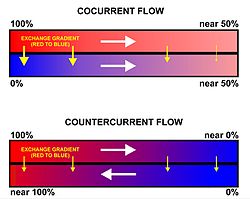
A comparison between the operations and effects of a cocurrent and a countercurrent flow exchange organisation is depicted past the upper and lower diagrams respectively. In both it is causeless (and indicated) that ruby-red has a higher value (e.g. of temperature) than bluish and that the belongings being transported in the channels therefore flows from ruddy to bluish. Note that channels are contiguous if effective exchange is to occur (i.east. there can exist no gap betwixt the channels).
There are three main types of flows in a spiral rut exchanger:
- Counter-current Catamenia: Fluids flow in opposite directions. These are used for liquid-liquid, condensing and gas cooling applications. Units are ordinarily mounted vertically when condensing vapour and mounted horizontally when handling high concentrations of solids.
- Spiral Catamenia/Cross Flow: Ane fluid is in spiral flow and the other in a cantankerous flow. Screw flow passages are welded at each side for this type of spiral rut exchanger. This type of menstruum is suitable for handling low density gas, which passes through the cross catamenia, avoiding pressure loss. It can exist used for liquid-liquid applications if one liquid has a considerably greater menses rate than the other.
- Distributed Vapour/Spiral flow: This blueprint is that of a condenser, and is ordinarily mounted vertically. It is designed to cater for the sub-cooling of both condensate and not-condensables. The coolant moves in a spiral and leaves via the elevation. Hot gases that enter leave as condensate via the bottom outlet.
Applications [edit]
The Spiral heat exchanger is expert for applications such as pasteurization, digester heating, heat recovery, pre-heating (come across: recuperator), and effluent cooling. For sludge treatment, SHEs are generally smaller than other types of heat exchangers.[ citation needed ] These are used to transfer the heat.
Selection [edit]
Due to the many variables involved, selecting optimal heat exchangers is challenging. Hand calculations are possible, merely many iterations are typically needed. As such, heat exchangers are most often selected via computer programs, either by system designers, who are typically engineers, or by equipment vendors.
To select an advisable oestrus exchanger, the organization designers (or equipment vendors) would firstly consider the design limitations for each heat exchanger type. Though cost is often the principal criterion, several other pick criteria are important:
- High/depression pressure limits
- Thermal functioning
- Temperature ranges
- Product mix (liquid/liquid, particulates or high-solids liquid)
- Pressure drops across the exchanger
- Fluid menstruation capacity
- Cleanability, maintenance and repair
- Materials required for construction
- Ability and ease of future expansion
- Material selection, such equally copper, aluminium, carbon steel, stainless steel, nickel alloys, ceramic, polymer, and titanium.
Small-diameter coil technologies are condign more than popular in mod air workout and refrigeration systems because they have better rates of heat transfer than conventional sized condenser and evaporator coils with round copper tubes and aluminum or copper fin that take been the standard in the HVAC manufacture. Small diameter coils tin withstand the college pressures required by the new generation of environmentally friendlier refrigerants. Two small diameter coil technologies are currently available for air conditioning and refrigeration products: copper microgroove[26] and brazed aluminum microchannel.[ commendation needed ]
Choosing the right heat exchanger (HX) requires some knowledge of the unlike heat exchanger types, equally well as the surroundings where the unit must operate. Typically in the manufacturing industry, several differing types of rut exchangers are used for only 1 process or organization to derive the concluding production. For example, a kettle HX for pre-heating, a double pipe HX for the 'carrier' fluid and a plate and frame HX for last cooling. With sufficient knowledge of heat exchanger types and operating requirements, an appropriate selection tin can be made to optimise the process.[27]
Monitoring and maintenance [edit]
Online monitoring of commercial heat exchangers is done by tracking the overall heat transfer coefficient. The overall estrus transfer coefficient tends to decline over time due to fouling.
By periodically calculating the overall rut transfer coefficient from exchanger catamenia rates and temperatures, the owner of the rut exchanger can estimate when cleaning the heat exchanger is economically bonny.
Integrity inspection of plate and tubular heat exchanger tin exist tested in situ by the conductivity or helium gas methods. These methods confirm the integrity of the plates or tubes to prevent any cross contagion and the status of the gaskets.
Mechanical integrity monitoring of heat exchanger tubes may be conducted through Nondestructive methods such as eddy electric current testing.
Fouling [edit]

A estrus exchanger in a steam power station contaminated with macrofouling.
Fouling occurs when impurities eolith on the oestrus substitution surface. Deposition of these impurities can decrease rut transfer effectiveness significantly over time and are caused by:
- Low wall shear stress
- Low fluid velocities
- High fluid velocities
- Reaction product solid atmospheric precipitation
- Precipitation of dissolved impurities due to elevated wall temperatures
The rate of heat exchanger fouling is determined by the charge per unit of particle deposition less re-entrainment/suppression. This model was originally proposed in 1959 by Kern and Seaton.
Rough Oil Exchanger Fouling. In commercial crude oil refining, crude oil is heated from 21 °C (70 °F) to 343 °C (649 °F) prior to entering the distillation column. A serial of shell and tube heat exchangers typically commutation oestrus between crude oil and other oil streams to heat the crude to 260 °C (500 °F) prior to heating in a furnace. Fouling occurs on the crude side of these exchangers due to asphaltene insolubility. The nature of asphaltene solubility in crude oil was successfully modeled by Wiehe and Kennedy.[28] The precipitation of insoluble asphaltenes in crude preheat trains has been successfully modeled as a first gild reaction by Ebert and Panchal[29] who expanded on the work of Kern and Seaton.
Cooling Water Fouling. Cooling h2o systems are susceptible to fouling. Cooling h2o typically has a high total dissolved solids content and suspended colloidal solids. Localized precipitation of dissolved solids occurs at the heat exchange surface due to wall temperatures college than bulk fluid temperature. Low fluid velocities (less than iii ft/s) allow suspended solids to settle on the rut exchange surface. Cooling water is typically on the tube side of a shell and tube exchanger considering it'southward like shooting fish in a barrel to clean. To preclude fouling, designers typically ensure that cooling h2o velocity is greater than 0.9 m/due south and majority fluid temperature is maintained less than 60 °C (140 °F). Other approaches to command fouling command combine the "blind" application of biocides and anti-scale chemicals with periodic lab testing.
Maintenance [edit]
Plate and frame heat exchangers tin can be disassembled and cleaned periodically. Tubular heat exchangers tin be cleaned by such methods as acid cleaning, sandblasting, high-pressure water jet, bullet cleaning, or drill rods.
In large-scale cooling water systems for oestrus exchangers, water treatment such as purification, add-on of chemicals, and testing, is used to minimize fouling of the heat exchange equipment. Other water treatment is also used in steam systems for power plants, etc. to minimize fouling and corrosion of the oestrus exchange and other equipment.
A multifariousness of companies have started using h2o borne oscillations technology to forbid biofouling. Without the apply of chemicals, this type of technology has helped in providing a depression-pressure drop in heat exchangers.
In nature [edit]
Humans [edit]
The human nasal passages serve as a heat exchanger, with absurd air beingness inhaled and warm air existence exhaled. Its effectiveness can be demonstrated by putting the hand in front end of the face and exhaling, showtime through the olfactory organ and then through the mouth. Air exhaled through the nose is substantially cooler.[thirty] [31] This issue tin be enhanced with vesture, by, for example, wearing a scarf over the face while animate in common cold weather.
In species that take external testes (such as human), the avenue to the testis is surrounded past a mesh of veins called the pampiniform plexus. This cools the blood heading to the testes, while reheating the returning claret.
Birds, fish, marine mammals [edit]

Counter-current exchange conservation circuit
"Countercurrent" heat exchangers occur naturally in the circulation organisation of fish, whales and other marine mammals. Arteries to the peel carrying warm blood are intertwined with veins from the skin conveying cold blood, causing the warm arterial blood to exchange estrus with the cold venous blood. This reduces the overall heat loss in cold h2o. Heat exchangers are also present in the tongue of baleen whales as big volume of water flow through their mouths.[32] [33] Wading birds utilise a like system to limit oestrus losses from their torso through their legs into the water.
Carotid rete [edit]
The carotid rete is a counter-current rut exchanging organ in some ungulates. The claret ascending the carotid arteries on its way to the encephalon, flows via a network of vessels where heat is discharged to the veins of cooler blood descending from the nasal passages. The carotid rete allows Thomson'due south gazelle to maintain its brain almost 3 °C (5.4 °F) cooler than the rest of the trunk, and therefore aids in tolerating bursts in metabolic heat product such as associated with outrunning cheetahs (during which the trunk temperature exceeds the maximum temperature at which the encephalon could part).[34]
In manufacture [edit]
Rut exchangers are widely used in industry both for cooling and heating large scale industrial processes. The type and size of oestrus exchanger used can exist tailored to suit a process depending on the type of fluid, its phase, temperature, density, viscosity, pressures, chemical composition and various other thermodynamic properties.
In many industrial processes in that location is waste matter of energy or a estrus stream that is being wearied, heat exchangers can be used to recover this heat and put it to use by heating a unlike stream in the process. This practice saves a lot of money in industry, as the heat supplied to other streams from the heat exchangers would otherwise come from an external source that is more expensive and more harmful to the environment.
Oestrus exchangers are used in many industries, including:
- Waste water treatment
- Refrigeration
- Wine and beer making
- Petroleum refining
- Nuclear power
In waste water treatment, heat exchangers play a vital role in maintaining optimal temperatures within anaerobic digesters to promote the growth of microbes that remove pollutants. Common types of heat exchangers used in this application are the double pipe oestrus exchanger as well equally the plate and frame heat exchanger.
In aircraft [edit]
In commercial aircraft oestrus exchangers are used to take heat from the engine'due south oil organisation to heat common cold fuel.[35] This improves fuel efficiency, besides as reduces the possibility of water entrapped in the fuel freezing in components.[36]
Manufacturing heat exchangers poses unique challenges for aerospace manufacturers. While high aspect ratios, thin walls, and tight spacing tin can all increment the heat exchanger's efficiency, such complex geometries tin be difficult to achieve for aerospace manufacturers, specially in materials compatible with high temperature applications such every bit engines.[37]
Current market and forecast [edit]
Estimated at US$42.7 billion in 2022, the global demand of oestrus exchangers will experience robust growth of about 7.8% annually over the adjacent years. The market value is expected to reach US$57.9 billion by 2022 and to arroyo United states$78.16 billion past 2022. Tubular oestrus exchangers and plate oestrus exchangers are notwithstanding the most widely applied product types.[38]
A model of a elementary heat exchanger [edit]
A simple heat exchange [39] [40] might be idea of equally two directly pipes with fluid flow, which are thermally continued. Let the pipes be of equal length 50, carrying fluids with oestrus capacity (energy per unit mass per unit modify in temperature) and let the mass flow rate of the fluids through the pipes, both in the same management, exist (mass per unit of measurement time), where the subscript i applies to pipe 1 or pipe 2.


Temperature profiles for the pipes are and where x is the altitude along the pipe. Assume a steady state, so that the temperature profiles are not functions of fourth dimension. Assume also that the only transfer of heat from a small volume of fluid in 1 pipe is to the fluid element in the other pipe at the same position, i.due east., in that location is no transfer of rut along a pipe due to temperature differences in that pipe. By Newton's police force of cooling the charge per unit of change in energy of a pocket-sized volume of fluid is proportional to the difference in temperatures between it and the corresponding element in the other pipe:


( this is for parallel catamenia in the aforementioned direction and opposite temperature gradients, just for counter-flow estrus substitution countercurrent substitution the sign is opposite in the second equation in front of ), where is the thermal energy per unit length and γ is the thermal connection constant per unit length between the ii pipes. This change in internal energy results in a modify in the temperature of the fluid chemical element. The time charge per unit of change for the fluid chemical element existence carried along by the flow is:


where is the "thermal mass catamenia rate". The differential equations governing the heat exchanger may now be written as:


Note that, since the system is in a steady country, there are no partial derivatives of temperature with respect to time, and since there is no heat transfer along the pipe, there are no second derivatives in x as is found in the estrus equation. These two coupled first-guild differential equations may exist solved to yield:


where , ,


(this is for parallel-flow, but for counter-flow the sign in front of is negative, then that if , for the same "thermal mass flow charge per unit" in both reverse directions, the slope of temperature is constant and the temperatures linear in position x with a constant departure along the exchanger, explaining why the counter current design countercurrent exchange is the well-nigh efficient )


and A and B are two as all the same undetermined constants of integration. Let and be the temperatures at x=0 and let and exist the temperatures at the end of the pipe at 10=L. Define the average temperatures in each pipage as:


Using the solutions above, these temperatures are:
Choosing any two of the temperatures higher up eliminates the constants of integration, letting united states find the other four temperatures. We find the total free energy transferred by integrating the expressions for the fourth dimension rate of change of internal energy per unit of measurement length:


Past the conservation of energy, the sum of the 2 energies is goose egg. The quantity is known equally the Log mean temperature deviation, and is a measure of the effectiveness of the estrus exchanger in transferring heat energy.

See as well [edit]
- Architectural engineering
- Chemical engineering
- Cooling tower
- Copper in heat exchangers
- Heat pipe
- Heat pump
- Oestrus recovery ventilation
- Jacketed vessel
- Log hateful temperature deviation (LMTD)
- Marine heat exchangers
- Mechanical technology
- Micro estrus exchanger
- Moving bed heat exchanger
- Packed bed and in item Packed columns
- Pumpable ice technology
- Reboiler
- Recuperator, or cross plate heat exchanger
- Regenerator
- Run around coil
- Steam generator (nuclear power)
- Surface condenser
- Toroidal expansion articulation
- Thermosiphon
- Thermal wheel, or rotary rut exchanger (including enthalpy wheel and desiccant wheel)
- Tube tool
- Waste heat
References [edit]
- ^ Al-Sammarraie, Ahmed T.; Vafai, Kambiz (2017). "Heat transfer augmentation through convergence angles in a pipe". Numerical Heat Transfer, Part A: Applications. 72 (iii): 197–214. Bibcode:2017NHTA...72..197A. doi:10.1080/10407782.2017.1372670. S2CID 125509773.
- ^ Sadik Kakaç; Hongtan Liu (2002). Heat Exchangers: Option, Rating and Thermal Design (2nd ed.). CRC Press. ISBN978-0-8493-0902-i.
- ^ Farzaneh, Mahsa; Forouzandeh, Azadeh; Al-Sammarraie, Ahmed T.; Salimpour, Mohammad Reza (2019). "Constructal Blueprint of Round Multilayer Microchannel Heat Sinks". Journal of Thermal Science and Engineering Applications. xi. doi:ten.1115/i.4041196.
- ^ a b Saunders, E. A. (1988). Heat Exchanges: Option, Design and Construction. New York: Longman Scientific and Technical.
- ^ a b "MICROCHANNEL Applied science" (PDF). Archived from the original (PDF) on June 4, 2022.
- ^ Kister, Henry Z. (1992). Distillation Design (1st ed.). McGraw-Hill. ISBN978-0-07-034909-iv.
- ^ Perry, Robert H.; Light-green, Don West. (1984). Perry's Chemic Engineers' Handbook (6th ed.). McGraw-Hill. ISBN978-0-07-049479-4.
- ^ Air Pollution Control Orientation Form from website of the Air Pollution Training Constitute
- ^ Energy savings in steam systems Archived 2007-09-27 at the Wayback Auto Effigy 3a, Layout of surface condenser (scroll to page 11 of 34 PDF pages)
- ^ Coulson, J. & Richardson, J. (1983), Chemical Engineering science – Pattern (SI Units), Volume half dozen, Pergamon Press, Oxford.
- ^ Hewitt G, Shires G, Bott T (1994), Process Heat Transfer, CRC Press Inc, Florida.
- ^ Table: Diverse Types of Gas – Liquid Directly Contact Heat Exchangers (Hewitt 1000, Shires G & Bott T, 1994)
- ^ Kee Robert J.; et al. (2011). "The design, fabrication, and evaluation of a ceramic counter-flow microchannel heat exchanger". Applied Thermal Engineering. 31 (11): 2004–2012. doi:x.1016/j.applthermaleng.2011.03.009.
- ^ Northcutt B.; Mudawar I. (2012). "Enhanced design of cross-flow microchannel heat exchanger module for loftier-performance aircraft gas turbine engines". Journal of Heat Transfer. 134 (6): 061801. doi:10.1115/i.4006037.
- ^ Moallem E.; Padhmanabhan S.; Cremaschi L.; Fisher D. E. (2012). "Experimental investigation of the surface temperature and water retentivity furnishings on the frosting functioning of a compact microchannel heat exchanger for heat pump systems". International Journal of Refrigeration. 35 (1): 171–186. doi:10.1016/j.ijrefrig.2011.08.010.
- ^ Sarvar-Ardeh, Southward., Rafee, R., Rashidi, S. (2021). Hybrid nanofluids with temperature-dependent properties for use in double-layered microchannel heat sink; hydrothermal investigation. Journal of the Taiwan Constitute of Chemic Engineers. cite periodical https://doi.org/10.1016/j.jtice.2021.05.007
- ^ Xu, B., Shi, J., Wang, Y., Chen, J., Li, F., & Li, D. (2014). Experimental Study of Fouling Functioning of Ac System with Microchannel Oestrus Exchanger.
- ^ Patent 2,046,968 John C Raisley issued July seven, 1936; filed Jan. viii, 1934 [1]
- ^ a b c d Patil, Ramachandra Grand.; Shende, B.W.; Ghosh, Prasanfa K. (xiii December 1982). "Designing a helical-whorl heat exchanger". Chemic Engineering. 92 (24): 85–88. Retrieved 14 July 2022.
- ^ a b Haraburda, Scott S. (July 1995). "Three-Phase Flow? Consider Helical-Whorl Oestrus Exchanger". Chemical Engineering. 102 (vii): 149–151. Retrieved 14 July 2022.
- ^ Us 3805890, Boardman, Charles Eastward. & Germer, John H., "Helical Coil Estrus Exchanger", issued 1974
- ^ Rennie, Timothy J. (2004). Numerical And Experimental Studies Of A Doublepipe Helical Estrus Exchanger (PDF) (Ph.D.). Montreal: McGill Academy. pp. 3–4. Retrieved 14 July 2022.
- ^ Rennie, Timothy J.; Raghavan, Vijaya Thou.S. (September 2005). "Experimental studies of a double-pipe helical heat exchanger". Experimental Thermal and Fluid Science. 29 (viii): 919–924. doi:x.1016/j.expthermflusci.2005.02.001.
- ^ "Cooling Text". Archived from the original on 2009-02-09. Retrieved 2019-09-09 .
- ^ E.A.D.Saunders (1988). Heat Exchangers:Selection Pattern And Construction Longman Scientific and Technical ISBN 0-582-49491-v
- ^ Microgroove: The Microgroove advantage; http://www.microgroove.cyberspace/
- ^
- White, F.M. 'Heat and Mass Transfer' © 1988 Addison-Wesley Publishing Co. pp. 602–604
- Rut Exchangers Archived 2008-03-29 at the Wayback Machine Kevin D. Rafferty, Factor Culver Geo-Heat Middle, 1996–2001 Final Accessed 17/3/08
- For manufacturing engineers who utilize rut processing equipment- Heat exchanger basics, BNP Media, 2007 Final Accessed 17/three/08
- ^ Wiehe, Irwin A.; Kennedy, Raymond J. (1 January 2000). "The Oil Compatibility Model and Crude Oil Incompatibility". Energy & Fuels. 14 (1): 56–59. doi:10.1021/ef990133+.
- ^ Panchal C;B; and Ebert W., Analysis of Exxon Crude-Oil-Skid-Stream Coking Data, Proc of Fouling Mitigation of Industrial Rut-Exchanger Equipment, San Luis Obispo, California, United states, p 451, June 1995
- ^ Heat Loss from the Respiratory Tract in Cold, Defense Technical Information Center, April 1955
- ^ Randall, David J.; Warren W. Burggren; Kathleen French; Roger Eckert (2002). Eckert animal physiology: mechanisms and adaptations . Macmillan. p. 587. ISBN978-0-7167-3863-3.
- ^ "Natural History Museum: Inquiry & Collections: History". Archived from the original on 2009-06-14. Retrieved 2019-09-09 .
- ^ Heyning and Mead; Mead, JG (November 1997). "Thermoregulation in the Mouths of Feeding Gray Whales". Science. 278 (5340): 1138–1140. Bibcode:1997Sci...278.1138H. doi:10.1126/science.278.5340.1138. PMID 9353198.
- ^ "Carotid rete cools brain : Thomson's Gazelle".
- ^ "United States Patent 4498525, Fuel/oil heat exchange arrangement for an engine". Us Patent and Trademark Role. Retrieved 3 February 2009.
- ^ "Boeing links Heathrow, Atlanta Trent 895 engine rollbacks". FlightGlobal.com. Retrieved iii February 2009.
- ^ Abolafia, Kirk. "Forming Estrus Exchangers Using Electrochemical Machining". Voxel Innovations.
- ^ "Market Report: Global Heat Exchanger Market". Acmite Market Intelligence. Oct 2022.
- ^ Kay J M & Nedderman R 1000 (1985) Fluid Mechanics and Transfer Processes, Cambridge Academy Press
- ^ "MIT web course on Heat Exchangers". [MIT].
- Coulson, J. and Richardson, J (1999). Chemical Engineering- Fluid Catamenia. Heat Transfer and Mass Transfer- Volume 1; Reed Educational & Professional Publishing LTD
- Dogan Eryener (2005), 'Thermoeconomic optimization of baffle spacing for beat out and tube oestrus exchangers', Energy Conservation and Management, Volume 47, Upshot 11–12, Pages 1478–1489.
- Grand.F.Hewitt, G.50.Shires, T.R.Bott (1994) Process Oestrus Transfer, CRC Press, Inc, United States Of America.
External links [edit]
- Heat Exchangers at Curlie
- Shell and Tube Heat Exchanger Pattern Software for Educational Applications (PDF)
- European union Pressure Equipment Guideline
- A Thermal Management Concept For More Electric Aircraft Power System Application (PDF)

Source: https://en.wikipedia.org/wiki/Heat_exchanger
Posted by: carmichaelshad1981.blogspot.com
0 Response to "How To Clean A Sooted Secondary Heat Exchanger"
Post a Comment